Introduction.
The analysis of electrical signals is in many applications. The different instruments which are used for signal analysis are wave analysers, distortion analysers spectrum analysers audio analysers and modulation analysers. All the signal analysis instruments measure the basic frequency of the signal, but they use different techniqes to do so.
1.the operating range of analysers . . .Spectrum analysers - 0.02 Hz - 250 GHz (Amplitude verses Frequency )
Wave analyser - 10 Hz - 40 MHz
Distortion analyser - 5 Hz - 1 MHz ( And give a measure of the energy present in a signal outside in a specified frequency band )
2. Wave analysers . . .
It is known that any periodic waveform can be represent as the sum of a d.c. component and series of sinusoidal harmonics. Analysis of a waveform consists of dieermination of the value of amplitude, frequency and sometime phase angle of the harmonic components. Graphical and mathematical methods may be used for the purpose but these methods are quite laborious.
A wave analyser in fact , is an instrument designed to measure relative amplitude of single frequency components in a complex waveform. The desired frequency is selected by frequency calibrated dial to the points of maximum amplitude. The amplitude is indicated either by a suitable voltmeter or a CRO.
Frequency selective wave analyser . . .
This wave analyser is used for measurements in the audio frequency range ( i.e 20 Hz - 20 KHz )
The analyser has a filter section with a very narrow passband which can tuned to the frequency of interest
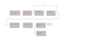
The waveform analyser to be analyzed in terms of its seperate frequency components is applied to an input attenuator that is set by a meter range switch on the front pannal. A driver amplifier feeds the attenuated waveform to high-Q active filter. The filter consist of a cascade arrangement of RC resonant sections and filter amplifiers. The passband of the total filter section is covered in decade steps over the entire audio range by switching capacitors in the RC sections.
 8:16 PM
 Sam
Sam

 Posted in


0 comments:
Post a Comment